
Plural-component chemical dispensing relies entirely on strict thermodynamic and hydraulic balance. When processing reactive polyurethane foams and elastomeric polyurea, maintaining chemical stability from the primary proportioner to the impingement mixing chamber presents significant fluid engineering challenges. Ambient temperature dissipation, hydraulic friction, and pressure loss across extended distribution runs threaten system equilibrium. Within this operational framework, the spray foam heated hose functions not merely as a fluid conduit, but as an active thermodynamic component engineered to control chemical viscosity, maintain stoichiometric ratio balance, and ensure complete molecular crosslinking at the mixing gun.
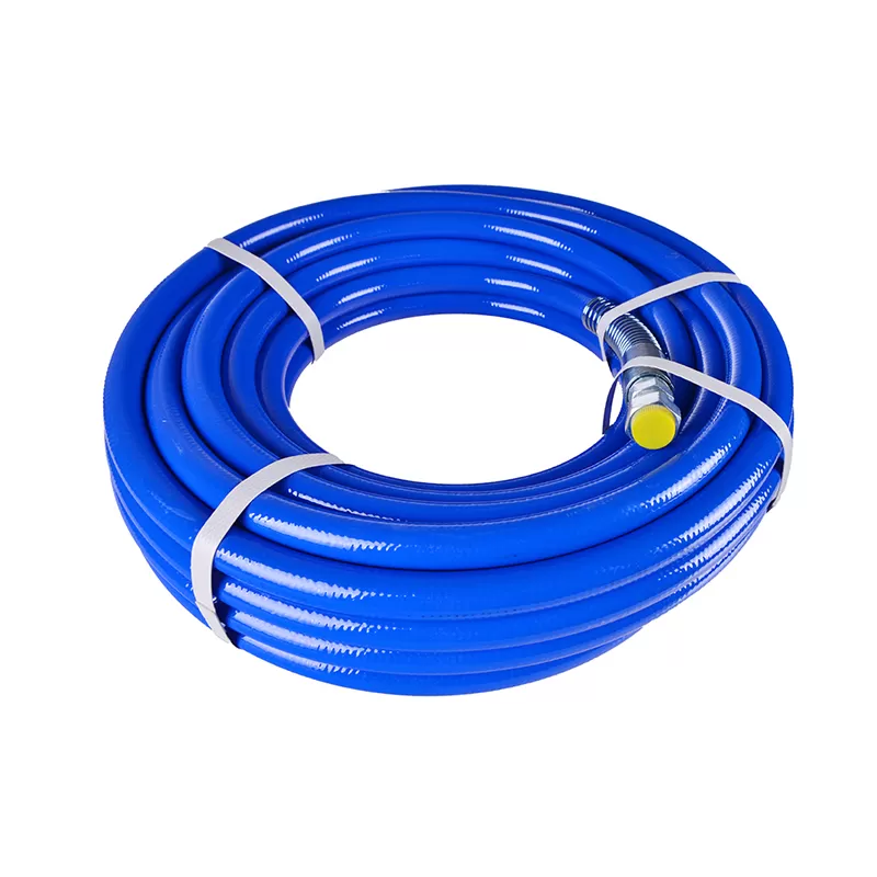
Thermodynamic Mechanics of High-Pressure Fluid Transfer
Polyurethane foam formulations consist of two chemically distinct components: Side A (typically polymeric methylene diphenyl diisocyanate, or pMDI) and Side B (a formulated blend of polyols, catalysts, blowing agents, flame retardants, and surfactants). These compounds exhibit markedly different viscosity-temperature curves. Unheated pMDI displays higher flow resistance at lower temperatures, whereas formulated polyols often possess steep viscosity gradients influenced by blowing agent concentrations, particularly with modern low-GWP hydrofluoroolefin (HFO) blowing agents.
When chemicals depart the primary preheaters of a high-pressure proportioner, they enter the delivery line at targeted processing temperatures—commonly between 110°F and 145°F (43°C to 63°C). Without continuous thermal energy compensation along the run, laminar flow dynamics cause rapid temperature decay. The fluid layers in contact with the inner conduit wall cool faster than the core stream, creating radial temperature gradients and localized viscosity spikes. This uneven flow profile increases friction loss, elevates mechanical load on the proportioner fluid section, and shifts dynamic pressures out of balance.
An engineered spray foam heated hose counteracts heat loss through controlled thermal conduction. By supplying steady wattage along the fluid path, the delivery system eliminates internal temperature variations. This dynamic thermal preservation ensures both chemical streams arrive at the spray gun chamber at matching viscosities, enabling clean impingement mixing at operating pressures between 1,200 and 2,500 psi.
Internal Architecture and Component Engineering
The structural integrity of a high-pressure transfer line requires layered, synergistic engineering. Because these assemblies endure high operating pressures, repeated mechanical flexing, thermal cycling, and rough jobsite handling, each internal layer serves a specific mechanical or electrical purpose.
- Core Fluid Conductors: Industrial lines utilize high-density polyamide or extruded PTFE cores rated for chemical compatibility with aromatic isocyanates and aggressive polyol formulations. PTFE inner liners reduce fluid drag and resist isocyanate crystallization, which can adhere to rougher sub-surfaces and cause bore narrowing over time.
- High-Tensile Reinforcement: Surrounding the core conduit is a braided reinforcement package constructed from high-tensile aramid fiber or high-tensile steel wire. This matrix supports dynamic operating pressures up to 3,500 psi while providing burst protection margins exceeding four times the operational rating.
- Thermal Element Layer: Continuous resistance heating wires or copper-braided heating ribbons wrap around the reinforced core. Distributed resistance elements provide uniform heat transfer around the conduit circumference, preventing localized hot spots that can degrade chemical additives or scorch polyol blowing agents.
- Sensory and Control Wiring: Embedded thermocouple or resistance temperature detector (RTD) wiring runs parallel to the fluid paths, terminating at a Fluid Temperature Sensor (FTS) block placed close to the whip hose. This provides closed-loop feedback to the proportioner control unit.
- Dielectric and Thermal Insulation: Low-density closed-cell elastomeric foam insulation envelopes both chemical conduits, electrical cables, and air lines. This thermal barrier prevents heat loss to the ambient environment while protecting the electrical heating element from mechanical compression.
- External Abrasion Scuff Jacket: The outermost layer consists of heavy-duty woven polyamide or extruded thermoplastic polyurethane. This jacket resists scuffing, puncture, solvent exposure, and gravel abrasion as equipment moves through demanding industrial environments.
Equipment manufacturers like HVBAN design these assemblies to balance structural resilience with physical flexibility, ensuring operators maintain precise fluid control across long runs without causing operator fatigue or structural hose failures.
Fluid Viscosity Equilibrium and Stoichiometric Control
Impingement mixing relies on kinetic energy. The A and B components enter the mixing chamber through opposing micro-orifices at high velocity. The kinetic energy atomizes the streams and forces intimate molecular contact within milliseconds. For this reaction to proceed correctly, both streams must hit the chamber at matched velocities and volumetric ratios—typically 1:1 by volume.
If thermal control drops along an unheated or poorly heated line, the cooler fluid's viscosity rises according to the Hagen-Poiseuille relationship for laminar pipe flow:
ΔP = (8μLQ) / (πR4)
Where ΔP represents the pressure drop, μ is dynamic fluid viscosity, L is line length, Q is volumetric flow rate, and R is inner conduit radius. Because dynamic viscosity (μ) increases non-linearly as temperature falls, a slight temperature drop causes a significant pressure drop across a 150-foot or 300-foot run.
When one chemical stream experiences higher pressure drop than the other, the proportioner fluid section encounters hydraulic resistance imbalances. The lower-viscosity chemical moves faster, while the higher-viscosity line lags, creating an off-ratio condition. This imbalance causes common curing defects:
- Excess Isocyanate: Results in brittle foam matrices, poor substrate adhesion, friable surfaces, and unreacted isocyanate migrating through the structure.
- Excess Polyol: Produces soft, spongy foam with open cell structures, dimensional shrinking, slow gel times, and prolonged surface tackiness.
- Density Shifts: Alters cell structure geometry, degrading the stated R-value per inch and reducing compressive strength under load.
Integrating a properly calibrated spray foam heated hose eliminates these viscosity variances, maintaining matching dynamic pressures across both conduits from the fluid pumps straight to the gun tip.
Electrical Trace Heating Architecture and Power Distribution
Heated hose lines rely on low-voltage, high-current resistance heating circuits powered by isolation transformers built into the primary proportioning unit. Operating voltages generally range from 24V up to 120V depending on total run length, keeping operator environments secure while delivering necessary wattage.
Direct-resistance heating relies on continuous copper or alloy conductors with predictable electrical resistance profiles (measured in ohms per foot). As alternating current flows through the circuit, resistive losses convert electrical energy directly into thermal energy, which transfers through the reinforcement layer into the chemical core. Maintaining consistent electrical resistance across hose joints requires heavy-duty terminal blocks and copper distribution plates that preserve continuity even under repeated mechanical stress.
Power delivery systems must account for total line length. As extra 50-foot sections join the system, overall electrical circuit length increases. This alters total loop resistance and requires proportional transformer tap adjustments. Advanced plural-component machinery engineered by HVBAN incorporates automated variable-transformer control or solid-state relay switching to monitor loop resistance continuously. This automatic regulation stabilizes heat output across hose configurations up to 400 feet without requiring manual rewiring.
Pressure Ratings, Flow Dynamics, and Core Diameter Selection
Conduit sizing dictates the dynamic behavior of plural-component delivery systems. Industrial contractors generally choose between 3/8-inch and 1/2-inch internal diameter (ID) main lines, coupled with a 10-foot to 20-foot 1/4-inch ID whip hose for maneuverability.
3/8-Inch Internal Diameter Conduits
The 3/8-inch configuration represents the industry baseline for spray foam applications with aggregate hose runs under 200 feet. This size minimizes the internal fluid volume, which lowers chemical changeover waste and reduces startup recirculation times. However, the smaller cross-sectional area produces higher shear friction per linear foot. When operating in cold ambient conditions or running high-density formulations, fluid pumps must generate higher mechanical pressures to overcome internal drag.
1/2-Inch Internal Diameter Conduits
For installations extending beyond 200 feet, or for high-viscosity polyurea formulations, a 1/2-inch ID core becomes necessary. Expanding the core diameter from 3/8-inch to 1/2-inch increases the cross-sectional flow area by approximately 77%. Referring back to the Hagen-Poiseuille equation, flow resistance decreases inversely with the fourth power of the radius (R4). This wider bore cuts frictional pressure losses substantially, protects pump motors from excessive backpressure, and maintains balanced flow rates even through complex conduit setups. A 10-foot 1/4-inch whip hose can then be connected to the end of the spray foam heated hose assembly, giving the technician mechanical freedom at the point of application without raising upstream hydraulic resistance.
Field Durability, Mechanical Stress, and Wear Factors
Dispensing lines face harsh physical environments, including scaffold edges, steel studs, rough concrete slabs, and unconditioned crawlspaces. Prolonged field life depends on understanding the mechanical stresses that cause premature line failures.
Minimum bend radius is an important operational limit. Forcing a heated assembly through an excessively tight turn pinches the inner fluid core and strains the resistance heating wires. Repeated over-bending causes work hardening in copper elements, causing localized metal fatigue and open-circuit electrical faults. A minimum dynamic bend radius of 8 to 12 inches must be preserved throughout operation.
Abrasion against abrasive surfaces can quickly cut through cheap exterior coverings. High-grade braided ballistic nylon or thick extruded polyurethane jacketing resists sharp friction points. Thermal insulation must also maintain high compressive strength; squashed insulation creates thermal bridging paths where heat rapidly escapes into cold concrete or muddy ground, causing localized temperature drops along the hose run.
Moisture ingress through compromised outer jacketing presents another functional challenge. Atmospheric moisture migrating past the outer layer into isocyanate line connections reacts with trace chemicals, yielding solid polyurea crystal formations. These crystals cling to inner walls, restrict fluid passages, and plug spray gun impingement ports.
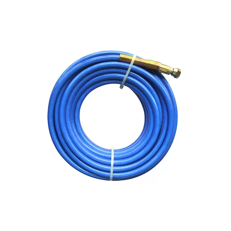
Troubleshooting Electrical and Fluid Continuity
System diagnostics require systematic isolation of fluid mechanics and electrical continuity:
- Diagnosing Open Electrical Loops: When a proportioner flags a hose heating error, check continuity using a digital multimeter set to resistance (ohms). Disconnect the hose loop from the transformer and probe the terminal pins. A reading of infinite resistance (OL) confirms a break in the heating element trace wire or a disconnected joint jumper. Check each 50-foot section's bridge connections to locate the broken segment.
- Diagnosing Fluid Temperature Sensor (FTS) Failures: Temperature sensing errors generally trace back to RTD or thermocouple signal wire damage near the whip hose junction, where dynamic movement is highest. A detached thermocouple wire prevents the central controller from reading chemical heat levels, triggering automatic shutdown protocols to prevent unheated off-ratio dispensing.
- Localized Temperature Variations: Cold spots along the line usually indicate collapsed insulation, wet insulation, or a failed bridge jumper across a modular hose section joint. Hot spots indicate bunched or overlapping trace heating wires, which concentrate electrical resistance in a small zone. Pinched wires must be serviced immediately to avoid melting inner conduits.
Systematic maintenance of your spray foam heated hose infrastructure preserves chemical consistency, protects proportioner hardware, and prevents costly material defects during application.
Frequently Asked Questions
How does a Fluid Temperature Sensor (FTS) communicate with the
primary proportioner?
The FTS assembly mounts between the end of the
main delivery hose and the flexible whip hose, placing its sensor probe directly
in contact with the moving chemical stream. It reads actual chemical temperature
rather than external conduit heat. Sensor data travels back to the proportioner
control system through embedded thermocouple or RTD wiring. The proportioner
evaluates these continuous readings and cycles transformer output to maintain
chemical setpoints regardless of fluctuating ambient temperatures.
What causes heating element burnout in modular hose
sections?
Burnout usually stems from mechanical fatigue, wire
overlap, or running electrical current through dry, empty hoses. Repeated sharp
bending causes work-hardening in copper trace wires, creating micro-fractures
that reduce cross-sectional wire area. These micro-fractures raise localized
electrical resistance, generating concentrated heat points that burn out the
element. Operating heated lines without fluid inside removes a vital heat sink,
causing core temperatures to spike beyond safe continuous ratings.
Can plural-component heated hoses be safely operated while partially
coiled?
No. Operating a heated hose line while coiled on a storage
rack or vehicle floor creates an induction core that traps concentrated heat.
Coiled runs cannot dissipate trace thermal energy safely, leading to melted
insulation, scorched chemical cores, and jacket degradation. Operators should
pull off all hose sections and lay them out in broad, sweeping patterns before
energizing the heating system.
Why is fluid pressure drop different between the A-Side and B-Side
conduits?
Isocyanate and polyol formulations have different chemical
backbones, molecular weights, and dynamic viscosities. Polyols are often
formulated with viscous polyester or polyether bases, making them more resistant
to flow than isocyanates at identical temperatures. Although both conduits share
identical lengths and inner diameters, higher polyol viscosity generates
increased wall friction, producing unequal pressure drops unless fluid
temperatures are balanced to align dynamic viscosities.
What seasonal maintenance maintains spray foam heated hose
performance?
Before long-term storage or seasonal commissioning,
check circuit resistance across each 50-foot segment using a calibrated
multimeter to confirm baseline resistance values. Inspect electrical jumper
pins, power connectors, and signal wires for corrosion or mechanical play. Clean
exterior scuff jackets, seal off exposed fluid manifolds with dry plastic plugs,
and flush lines with dedicated, non-crystallizing storage plasticizers to keep
internal seals soft and stop isocyanate crystal formation.
Technical Consultation and Equipment Specifications
Matching fluid delivery hardware to job specifications requires careful analysis of fluid viscosity, pump capacity, run length, and thermal draw. HVBAN manufactures high-performance fluid delivery solutions, plural-component proportioning equipment, and industrial spray systems engineered to handle demanding modern coatings and chemical formulations. Technical specialists are available to review system requirements, calculate electrical load profiles, and configure high-pressure transfer lines tailored to your operational needs. Contact our engineering team for technical specifications, product pricing, and tailored system configurations.