
High-volume protective coatings, architectural finishes, and marine-grade linings demand atomization systems that function without compressed air intervention. An industrial airless spray unit operates on a principle fundamentally distinct from pneumatic atomization systems. Rather than utilizing high-velocity air streams to shear a fluid column into droplets, airless equipment forces liquid coating through a precisely machined orifice under fluid pressures typically ranging between 1,500 and 5,000 pounds per square inch (100 to 345 bar). This hydraulic force converts potential energy into kinetic fluid velocity, shearing the coating material as it enters atmospheric pressure, creating a coherent, highly controlled spray pattern.
Industrial operations depend on precise transfer efficiency, reduced overspray, and high film builds per pass. Achieving these parameters requires a comprehensive understanding of hydraulic fluid dynamics, mechanical pump displacement mechanisms, packings assemblies, and fluid rheology under extreme pressure differentials.
Fluid Delivery Dynamics and the Hydraulic Atomization Process
When configuring an airless spray unit for production facilities, atomization quality is determined by the fluid velocity profile at the tip orifice and the structural properties of the applied formulation. Unlike conventional air spray methods where air-to-fluid ratios dictate droplet distribution, hydraulic atomization relies exclusively on the pressure drop across the nozzle.
Fluid exiting the orifice experiences immediate deceleration upon contact with ambient air. This shear forces the cohesive liquid sheet to oscillate and rapidly destabilize into ligaments, which subsequently break apart into fine spherical droplets. The equation governing this discharge rate relates directly to the cross-sectional area of the tip and the pressure differential:
Fluid flow rate depends directly on the discharge coefficient, the orifice cross-sectional area, fluid density, and the net pressure drop across the tip. High-viscosity coatings containing elevated solids require higher hydraulic pressure to reach the threshold velocity needed to overcome internal surface tension and yield stress.
Primary Atomization: The cohesive fluid sheet stretches and thins instantly as it exits the tungsten carbide tip geometry.
Secondary Droplet Formation: Aerodynamic drag destabilizes liquid ligaments, creating micro-droplets distributed across the designed fan width.
Pattern Tail Elimination: Insufficient fluid pressure leaves the outer edges of the spray fan without adequate energy, causing heavy streaks or "tails." Increasing hydraulic pressure or thinning the coating rectifies the velocity distribution across the fan perimeter.
Core Mechanical Assemblies within the Fluid Section
The operational longevity of industrial fluid handling machinery rests on the structural integrity of its wet end components. The reciprocating positive displacement piston pump serves as the standard mechanism within professional liquid transfer operations.
During the upward stroke of the displacement rod, the upper ball check seats against its carbide seal, creating a vacuum within the lower fluid chamber. This pressure differential lifts the inlet foot valve ball, drawing coating material upward into the displacement cylinder. During the downward stroke, the inlet ball seats securely to prevent backflow into the reservoir, while the piston ball check lifts, forcing fluid through the internal piston channel and out into the high-pressure fluid filter manifold.
Displacement Rod and Cylinder Tribology
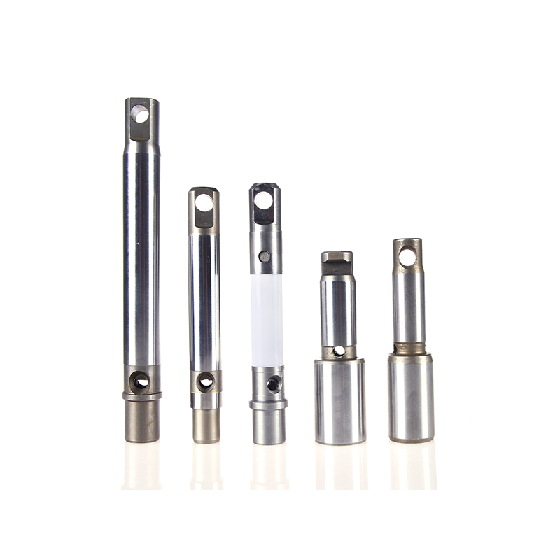
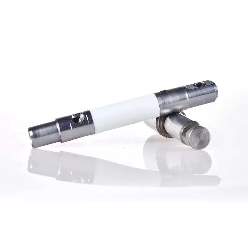
Continuous cycling under high pressure subjects the piston rod and cylinder sleeves to abrasive friction from mineral pigments, silica additives, and zinc flakes. Manufacturers like HVBAN incorporate heavy-duty chrome-plated fluid rods and heat-treated stainless steel cylinders to maintain dimensional tolerances under prolonged abrasive wear. Surface micro-finishing ensures that dynamic seal friction is kept low, preventing premature seal deterioration.
Dynamic V-Packing Seal Architecture
Fluid containment around the reciprocating rod relies on multi-layered dynamic packing sets. These configurations combine alternating rings of virgin PTFE, UHMWPE (Ultra-High-Molecular-Weight Polyethylene), and premium leather.
PTFE Components: Deliver thermal resilience and broad chemical compatibility with aggressive aromatic solvents, esters, and ketones.
UHMWPE Components: Provide high abrasion resistance against micro-particulate solids suspended in industrial primers.
Leather Seals: Retain throat seal lubricants, expanding slightly upon moisture absorption to maintain low-pressure sealing during initial suction cycles.
Tip Geometry, Orifice Sizing, and Fan Pattern Dynamics
Selection of the atomizing tip determines both wet film thickness and deposition speed. Airless tip nomenclature follows standard sizing conventions that dictate both pattern width and fluid output capacity.
A standard three-digit tip marking (such as 517) conveys specific operational parameters. The first digit represents half the total fan width at a distance of 12 inches (305 mm) from the substrate; multiplying this number by two yields a 10-inch fan pattern. The subsequent two digits denote the internal equivalent orifice diameter in thousandths of an inch (0.017 inches). As fluid passes through the elliptical carbide insert, flow volume scales non-linearly with orifice diameter expansion.
| Tip Sizing Code | Equivalent Orifice Size (Inches) | Fan Width at 12" Distance | Recommended Coating Viscosity |
|---|---|---|---|
| 311 - 413 | 0.011 - 0.013 | 6 to 8 Inches | Stains, Lacquers, Low-Viscosity Primers |
| 415 - 517 | 0.015 - 0.017 | 8 to 10 Inches | Architectural Emulsions, Acrylics, Enamels |
| 519 - 621 | 0.019 - 0.021 | 10 to 12 Inches | High-Build Epoxies, Block Fillers |
| 527 - 635 | 0.027 - 0.035 | 10 to 12 Inches | Elastomerics, Intumescent Fireproofing, Mastics |
Carbide orifice wear occurs gradually due to fluid erosion. As the abrasive particulate rounds the sharp internal edges of the ellipse, two things occur: the fan pattern narrows, and the volumetric output increases. A worn tip with an expanded orifice forces the pump to cycle faster to maintain pressure, increasing fuel or electrical draw and resulting in excessive material consumption.
Drive Mechanisms and Power Train Engineering
Matching an airless spray unit to specific site requirements involves assessing available utility infrastructure, operating environments, and duty cycle requirements.
Brushless DC Electric Motor Drives
Electric systems provide dependable operation for commercial architectural projects and industrial paint booths. Brushless DC motors deliver high torque output at low RPM, matching torque requirements directly to fluid section load variations. Electronic pressure control modules monitor fluid line pressure dynamically, adjusting motor speed via microprocessor controls to eliminate pressure pulsations at the spray gun.
Hydraulic-Driven Piston Systems
For heavy industrial and continuous duty cycles where high-viscosity coatings are standard, hydraulic piston systems provide steady linear thrust. Hydraulic fluid pressure acting on a larger hydraulic piston drives a smaller fluid section displacement rod, providing mechanical advantage ratios of 30:1 up to 75:1. The longer stroke length and slower cycling rate substantially reduce wear on packing seals, making these machines suited for continuous operation requirements where equipment from HVBAN matches long shift cycles.
Pneumatically Driven Pumps
In explosive environments such as offshore oil platforms, shipyards, and solvent-heavy fabrication shops, pneumatic fluid pumps eliminate electrical ignition hazards. Large-diameter air motors utilize compressed air to drive fluid sections, offering simple stalling characteristics when the fluid line valve is closed without damaging motor internals.
Managing High-Solids and Abrasive Protective Linings
Modern industrial coatings increasingly shift toward high-solids and 100% solids zero-VOC formulations to meet environmental requirements. These materials present significant fluid handling challenges, including rapid curing curves, high thixotropy, and high shear resistance.
Operating an airless spray unit with high-solids formulations demands fluid lines designed to handle extreme backpressures without structural dilation. Fluid hoses must feature continuous conductive grounding braids embedded between internal polyamide cores and external polyurethane covers to dissipate electrostatic charges generated by high-velocity fluid friction.
Thixotropic Breakdown: High-solids epoxies exhibit high initial viscosity at rest. Passing through the fluid manifold and high-pressure orifice applies extreme shear, lowering apparent viscosity and facilitating substrate wet-out.
Manifold Filtration Strategy: Staged filtration prevents nozzle clogging. Fluid should progress from a coarse rock catcher at the suction pipe, through a 60-mesh pump manifold filter, to an optional 100-mesh handle filter inside the gun body.
Thermal Management: In-line fluid heaters reduce the baseline viscosity of high-solids polyurethanes without introducing volatile chemical thinners, lowering the fluid pressure required for complete atomization.
Component Longevity and Fluid Section Maintenance
Consistent output from industrial spraying machinery requires structured preventative maintenance schedules focused on wear-part inspection and fluid path hygiene.
Throat seal liquid (TSL) must be maintained in the wet cup above the dynamic packing nut daily. This specialized plasticizer prevents dried coating materials from adhering to the reciprocating piston rod, which would otherwise cut the upper V-packings during the downstroke. Proper packing nut torque is equally vital; overtightening causes rapid friction-induced seal destruction, while undertightening allows fluid to bypass into the throat cup.
Complete fluid flushes must be conducted immediately following spray operations. Solvent selection must match the primary coating carrier, followed by a secondary flush with non-corrosive storage lubricants to prevent internal corrosion of tungsten carbide seats and chrome plating.
Frequently Asked Questions
What causes pressure fluctuations in an airless spray unit during operation?
Pressure drop during trigger engagement generally indicates an inlet suction issue, a worn pump packing set, or an oversized tip relative to the pump's displacement capacity. Inspect the inlet foot valve for debris lodged under the ball check, confirm the suction tube connection is airtight, and verify that the manifold filter screen is clean.
How does fluid viscosity affect tip selection and pump pressure settings?
Higher viscosity fluids possess higher internal shear resistance, requiring larger orifice diameters (e.g., 0.021 inches or larger) and higher hydraulic operating pressures to break the fluid column into a uniform fan. Lower viscosity coatings atomize efficiently with smaller orifices (e.g., 0.011 to 0.015 inches), which limits fluid delivery volume and prevents sags or runs.
What is the difference between direct immersion and suction hose configurations?
Direct immersion mounts the pump fluid end directly into or immediately above the coating drum, minimizing suction lift restrictions. This setup is preferred for heavy mastics and high-viscosity coatings. Flexible suction hose assemblies offer mobility for smaller containers but introduce minor vacuum restrictions when drawing highly viscous materials.
Why are tungsten carbide seats used instead of standard stainless steel in check valves?
Tungsten carbide exhibits extreme hardness and resistance to erosion caused by high-velocity fluid flow carrying abrasive pigments like titanium dioxide or zinc. Standard stainless steel components erode rapidly under identical high-pressure cycling, leading to loss of fluid prime and pressure drop.
How can static electricity hazards be managed during airless application?
Fluid moving through high-pressure hoses generates substantial static charges. Operators must use grounded, static-conductive fluid lines with integrated grounding wires, connect the pump grounding clamp directly to a true earth ground, and ensure metal receiving containers are bonded to the spray rig during fluid flushing.
Industrial Fluid Machinery Sourcing and OEM Consultation
Selecting fluid application machinery requires matching pump displacement capacity, drive motor power, and dynamic seal compositions directly to material specifications and production schedules. For contractors and distributors seeking to source a reliable airless spray unit, HVBAN delivers tailored production platforms, high-pressure fluid sections, and precision components manufactured to exacting industrial tolerances. Contact our fluid application engineering team with your coating specifications, operating volumes, and facility configurations to receive detailed equipment specifications and wholesale OEM integration quotes.